LED display @ Maker Faire
As already described in my article about the BeagleBone Black the project consists of several steps which all must work together to bring the display to life. The first step was to develop an hardware interface which was able to drive the LEDs from content generated by the BeagleBone Black. I decided to use an FPGA which acts like a memory device towards the BeagleBone Black so I could use its general purpose memory controller (GPMC). This is a very fast interface and also rather simple to implement on the FPGA side as I am using the FPGA's block RAM modules as a dual-port RAM. Using this approach no clock synchronisation is needed between the two devices. The FPGA then sends the pixel data using the HUB75 protocol towards the LED matrices. As a first prototype I used the LOGI-Bone, but then built my own PCB. With this first revision of the PCB, which was very similar to the LOGI-Bone, I managed to display data on 4 LED matrices and could show that my approach works.
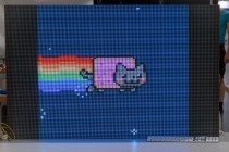
The next step was to decide the final size of the LED display. I opted for 8 × 5 modules of 32 × 32 pixels each with a 5 mm pixel pitch, which results in a resolution of 256 × 160 pixels and an aspect ratio of 16:10. The determining factors where
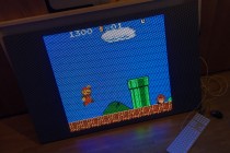
Super Mario
- At least 160 × 144 pixels resolution to be able to run a GameBoy emulator with native resolution
- A 16:10 or 16:9 aspect ratio for movies
- A manageable physical display size
- Less than 1k€ for LED modules
- Pixel data should fit into the FPGAs block RAM and the FPGA should be affordable and available in single quantities
As the 40 modules will need 80 kB of block RAM I choose a Xilinx Spartan 6 XC6SLX25-FTG256, which provides 52 block RAM modules of 18kbit each. As the I/O banks of the FPGA will run from 3.3V, but the ICs on the LED modules run from 5V, I added SN74ACT244 drivers to each output to have better voltage levels when using high frequencies on the HUB75 interface. This was one major thing I learnt from playing around with my first prototype. The XC6SLX25-FTG256 comes in an 256-pin BGA package and I had to use at least four layers for the PCB. You can find the complete schematics and gerbers for the PCB at the hardware repository.
First light with the second PCB
Copper busbar

Mounting all modules
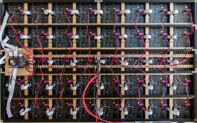
Everything wired up
After everything was built up I applied power, booted the BeagleBone Black and everything worked! But after five minutes the power supply started doing weird noises and died a few seconds later. What a bummer! I did some analysis and was pretty sure that everything was fine with my display and I was able to run it partly (one row at a time) from my bench power supply. So I ordered an MSP-600-5 5V 120A power supply from MeanWell as a spare part. I received it two days before the Maker Faire and with that power supply everything run fine.
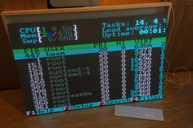
First test of the final setup
The next steps will be to fix minor issues (e.g. some ghosting) and improve the design (power supply supervision, measure power consumption, even more sturdiness, maybe HDMI input, ...).
Hi Tobias
great project and great work done by you.
I am also designing the same project but with some different approach, I think that it would be better to have some chat with you in this regard as you have done this project so I think you know all problems you encountered in advance and would be a lot of help for me.
hope you would accept my invitation please reply me with your response in this regard.
Thanks
Piyush Pandey
Hi Piyush!
Thanks for your comment! I'm happy to answer your questions regarding the project. Please feel free to ask here, so that anybody can profit from it, or send me an email (twamtwam.info) or pn on facebook/twitter. I spotted a similar project on 32C3 (https://wiki.hackerspace.pl/projects:q3kled) and this was motivation for me to continue on this project. So I actually started with a new approach to control with HDMI.
Tobias
Hi Tobias
First of all very much thanks for your reply 🙂
Actually I am doing this project from last year August month and till now I have completed a very small percentage of it.
But after having a look at your project I am very much hopeful that I will be able to finish this one as early as possible.
Please can you call me at my mail piyush.pandey.013@gmail.com
regards
Piyush Pandey
Hello Tobias
I am looking into making a LED display myself, and was wondering how much of the logic cells on the FPGA was used. thinking LUTs and flipflops since incorporating a Artnet receiver core take up a substantial amount of Logic cells in it self.
Thanks
Alexander
Usage statistics for the XC6SLX25-FTG256 are:
Hello Tobias,
I have interest in experimenting with your exact design so how much does it cost to make your prototype spartan board and which pcb company made it for you?
Thanks
The PCB was made by OSH Park and IIRC was around 100 $ (without components).
Hello Tobias,
Thanks, you are far too kind though as a fresh hobbyists I will have to explore options of avoiding 256 pins BGA package assembly but any advice will be very much welcome.
Thanks once again
Edogwu
120 amps!
hi Tobias great job is the one that has played, I have a doubt you think it would be appropriate or what difficulty would have to adapt your code to FPGA cyclone iv EP4CE6E22C8N, I would like you not to ignore my question and some help with hub75 protocol
Sadly, I do not know anything about Cyclone FPGA.
For the HUB75 protocol, there is a good example and explanation on http://bikerglen.com/projects/lighting/led-panel-1up/
thank you very much sir, for answering, because I will learn a lot, I still do not understand the BAM, my first steps with FPGA Cyclone IV, use ARM Cortex 3, but great work that you have drawn.
Hi Sir
I am very respect your work. it's so cool.
I am also new hand!
Now i start new job for 4x4 rgb panel 32x32
and lvds to hub75
could you give me suggest for 65M@1024x786
how to display on 4X4 hub75
Thanks
Hi Sir
I am very respect your work. it's so cool.
I am also new hand!
Now i start new job for 4x4 rgb panel 32x32
and lvds to hub75
could you give me suggest for 65M@1024x786