Today I received my new Linksys Router. It's WRT610N with two wifi cards inside. One for traditional 2.4 GHz 802.11b/g/n and one for 5 GHz 802.11a/n. I'm planning to use OpenWRT or some other non standard firmware on it, so I wanted to add the RS232 console port I had on my old WRT54GS. Here's how to use it:
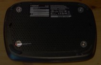
First, we have to remove 4 screws on the bottom of the case. You'll need a T10 TORX screwdriver for them.
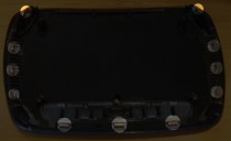
You we have to lift the cover. It has 11 points to snap in which have to carefully unsnap with a small screwdriver. It started in the middle of the front and unsnapped one from each side and so on.
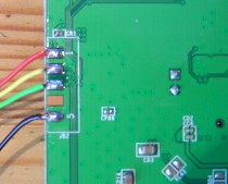
After unplugging the six antenna cables (Remember where each has been plugged into) you should be able to remove the board. On the bottom you should see 5 contacts in the upper left corner. It has the follow pin assignments:
| PIN | Signal |
|---|---|
| 1 | +3.3V |
| 2 | RS232 TX |
| 3 | RS232 RX |
| 4 | ? |
| 5 | GND |
I soldered a wire to pin 1,2,3 and 5 and run them in one of the holes in the bottom of the case.
The TX/RX pins have 3.3V level signals. To connect them to a standard RS232 port they have to be ±12V. The conversion is very easy, as there are several standard ICs for this purpose. I used an MAX3233 chip. It's datasheet shows a typical application on page 12:
I connected pin4 to TX, pin 6 to RX, pin 9/10 to +3.3V and pin 5/18 to GND. On the PC side you have to use a standard D-SUB9 female connector. Connected pin 5 of the connector to GND, pin 2 of the connector to pin 7 of the chip and pin 3 of the connector to pin 8 of the chip. That's all.
Now start your favorite terminal program, set it to 115200 8N1 and power on the Linksys. It should print something like
CFE version 1.0.37 for BCM947XX (32bit,SP,LE)
Build Date: Wed Jun 25 19:11:21 CST 2008 (ljh@team2-complier)
Copyright (C) 2000,2001,2002,2003 Broadcom Corporation.

Initializing Arena
Initializing PCI. [normal]
PCI bus 0 slot 0/0: vendor 0x14e4 product 0x0800 (flash memory, rev 0x02)
PCI bus 0 slot 1/0: vendor 0x14e4 product 0x471f (ethernet network, rev 0x02)
PCI bus 0 slot 2/0: vendor 0x14e4 product 0x471a (USB serial bus, interface 0x10, rev 0x02)
PCI bus 0 slot 2/1: vendor 0x14e4 product 0x471a (USB serial bus, interface 0x20, rev 0x02)
PCI bus 0 slot 3/0: vendor 0x14e4 product 0x471b (USB serial bus, rev 0x02)
PCI bus 0 slot 4/0: vendor 0x14e4 product 0x0804 (PCI bridge, rev 0x02)
PCI bus 0 slot 5/0: vendor 0x14e4 product 0x0816 (MIPS processor, rev 0x02)
PCI bus 0 slot 6/0: vendor 0x14e4 product 0x471d (IDE mass storage, rev 0x02)
PCI bus 0 slot 7/0: vendor 0x14e4 product 0x4718 (network/computing crypto, rev 0x02)
PCI bus 0 slot 8/0: vendor 0x14e4 product 0x080f (RAM memory, rev 0x02)
PCI bus 0 slot 9/0: vendor 0x14e4 product 0x471e (class 0xfe, subclass 0x00, rev 0x02)
Initializing Devices.

No DPN
This is a Parallel Flash
Boot partition size = 262144(0x40000)
Partition information:
boot    #00   00000000 -> 0003FFFF  (262144)
trx     #01   00040000 -> 0004001B  (28)
os      #02   0004001C -> 007F7FFF  (8093668)
nvram   #03   007F8000 -> 007FFFFF  (32768)
Partition information:
boot    #00   00000000 -> 0003FFFF  (262144)
trx     #01   00040000 -> 007F7FFF  (8093696)
nvram   #02   007F8000 -> 007FFFFF  (32768)
PCI bus 0 slot 1/0: pci_map_mem: attempt to map 64-bit region tag=0x800 @ addr=18010004
PCI bus 0 slot 1/0: pci_map_mem: addr=0x18010004 pa=0x18010000
ge0: BCM5750 Ethernet at 0x18010000
CPU type 0x2901A: 300MHz
Total memory: 65536 KBytes

Total memory used by CFE:  0x80700000 - 0x807A60E0 (680160)
Initialized Data:          0x8073A2E0 - 0x8073E570 (17040)
BSS Area:                  0x8073E570 - 0x807400E0 (7024)
Local Heap:                0x807400E0 - 0x807A40E0 (409600)
Stack Area:                0x807A40E0 - 0x807A60E0 (8192)
Text (code) segment:       0x80700000 - 0x8073A2E0 (238304)
Boot area (physical):      0x007A7000 - 0x007E7000
Relocation Factor:         I:00000000 - D:00000000

Boot version: v4.2
The boot is CFE


You obviously didn't spot the other serial port hidden in the WAN/Internet port. Cisco have a special debug adapter for it.
I saw it, but I didn't find any information how to get one and soldering there would have made the WAN/Internet port unuseable. If you know any source for the adapter, please let me know.
Pingback: » Recovering a Bricked Linksys WRT320N Router Money Pit Labs
I have a Bricked E2000 which it should be the same board as WRT610N. I have triied to sold the cables but i couldnt. Do you think you can share with me a picture of your cable and device that you used to get console access. Thanks
I'm sorry, but I don't own the device anymore.