A few weeks ago I bought the ATLYS FPGA development board from Digilent. Unlike my other two FPGA development boards (NEXYS3, BASYS2) the ATLYS does not have a 7-segment display onboard. As I often use this during debugging I wanted to add some external 7-segment display to the ATLYS board. The ATLYS boards provides two connections for add-on boards: A high-density Vmod port and a 8-pin Pmod™ port. As I'm planning to use the Vmod port for other stuff I wanted to use the Pmod™ port for the 7-segment display.
On my other two FPGA bords the 7-segment display is directly connected to the FPGA. The 4-digit 7-segment display has four anodes (one per digit) and eight cathodes (one per segment plus the decimal point) totalling in twelve pins. The display control has to be multiplexed within the FPGA. As the Pmod™ connector has only eight pins this kind of control mechanism would not work. So the most obvious alternative to send the data for pins serially and to use serial to parallel converters on the extension board. However I wanted to avoid using a lot of ICs on the boards so I went for an alternative approach: Charlieplexing.
Charlieplexing is an 'improved' version of multiplexing that uses the fact that all of the I/O pins of the FPGA are tristate pins. A good description of it can be found in Maxim's Application Note 1880.
Charlieplexing requires a little bit more logic inside the FPGA, but using the 8-pins of the Pmod™ connector it allowed me to address 56 leds, which results in eight 7-segment digits (without the decimal point).
During my research I found the StickIt!-LedDigits by XESS which basically did exactly what I wanted. However I didn't wanted to buy a complete solution, but build it myself. So I designed similar PCB and soldered it together. The board consists of a Pmod™ connector which fulfills the Digilent Pmod™ Interface Specification, eight 7-segment displays and eight resistors. For the usage with the ATLYS development board the resistors can be choosen to 0 Ω as the pins supply a maximum of 24 mA. The KiCad layout files can be found at the project repository.
The VHDL part for driven the display is not very complex. It basically iterates through all of the digits and segments and switches them on/off depending of the data to be displayed. It is important to note, that at every time only one LED is active and not a complete digit as in traditionally multiplexing. What makes the code look a little bit complex is that depending of the digit the segment numbering changes a little bit. The VDHL module for the display can be found here.
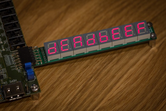
Pmod™ 8-digit 7-segment display
As you can see the display is working fine, but as the FPGA only supplies up to 24 mA for the LEDs and due to the fact that only one segment can be on at a time, the brightness of the display is quite dim. So depending on the usage this might not be an ideal solution, but for debugging purpose this fits quite well.
Thank you for your work. I have the XESS display module, and your code has helped me to understand how to get the charlieplexed scheme to work with an FPGA far better than the sample code from XESS. Could you offer some guidance in how I could turn off digits until needed? For example, if I only wanted one digit to be displayed for numbers 0-9, then activate a second digit for numbers 10-99, etc.
Thank you again
I would add an additional input vector
active_digits : in std_logic_vector(7 downto 0);
to the module and check for it in line 112 like
if active_digit(i) = '0' and active_digits(i)='1' then
Then it will only display something for a digit if the corresponding bit is set in active_digits. It still loops over all digits and thus the brightness stays the same.
I'm just starting to learn VHDL. I built my own charlieplexed display board that I could use while I learn how to work with FPGA boards. I think you can simplify the section that sets the values for the tristate vector.
The active_digit and active_segment vectors indicate which display board lines need to be driven while all other lines should be put in tristate mode. I don't know how a for loop would translate to logic but I think you simplify the VHDL by using
tristate <= NOT (active_digit OR active_segment);